PTC Creo 10.0.1.0 with HelpCenter Win x64
- ПРОГРАММЫ
- 2-08-2023, 13:33
- 186
- 0
- TUTBB

Free Download PTC Creo 10.0.1.0 with HelpCenter | 8.6 Gb
Languages Supported: * English, עברית, 日本語, Ελληνικά, Français, Türkçe, Deutsch, Čeština, Русский,
Polski, Italiano, Magyar, Español, Slovenščina, 한국어, Português, Traditional 中文,
Simplified 中文, Brazilian Português, Slovenčina
Owner:PTC
Product Name:Creo
Version:10.0.1.0 with Manikin Libraries & HelpCenter
Supported Architectures:x64
Website Home Page :www.ptc.com
Languages Supported:multilanguage
System Requirements:Windows *
Size:8.6 Gb
PTC has releasedCreo 10.0.1.0. Creo 10 helps you deliver your best designs in less time, with new composite tools and enhancements for electrification and ergonomics design, MBD, simulation-driven design, and manufacturing.
What's New Creo Parametric 10.0.1.0
Composite Design and Manufacturing
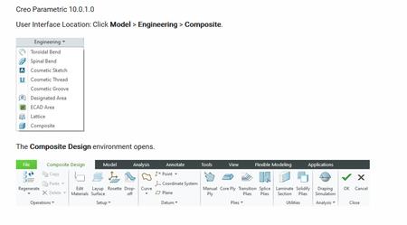
You can now use a new fully-integrated Composite Design environment in Creo to design and manufacture parts built using composite layups.
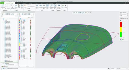
This enhancement enables you to design composite layups in Creo. It supports the complete composite design workflow that includes designing a composite layup, making laminate sections, adding ply transitions, splicing plies for manufacturing, running draping simulation, exporting flat pattern, running the integrated structural analysis, and creating a ply book.
Composite Material Definition
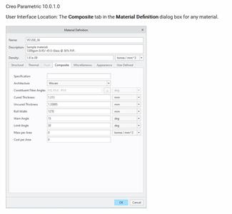
You can now use the new Composite tab in the Material Definition dialog box to specify the composite specific properties of a material. To use a material in the composite design process, you must at least define its Cured Thickness property. Other properties defined in the Composite tab add value throughout the composite design process. For example, the Roll Width, Warn Angle and Limit Angle properties are useful in a draping simulation. Set the new configuration option cmpst_mtrl_angular_prms_unit to control the default unit for angular properties in the Composite tab in the Material Definition dialog box. Several composite ply and core sample materials are provided with the Creo installation.
Defining composite material properties is useful when designing a composite structure in Creo. The new Composite tab in the Material Definition dialog box provides a centralized location for defining material details for the composite design.
Manual Ply
Creo Parametric 10.0.1.0
User Interface Location: In Composite Design, clickPlies > Manual Ply.
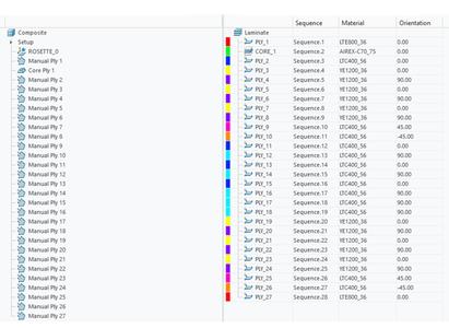
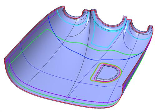
You can now use the new Manual Ply command to create a ply object in the Laminate Tree. A manual ply consists of a boundary chain, a material definition, a rosette coordinate system, an orientation angle, and the drop-off value. In addition to the required outer boundary loop, you can also include inner loops.
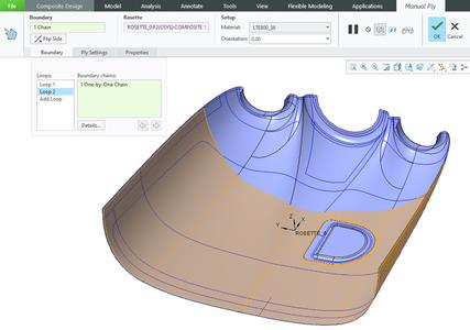
To set the default prefixes for the name and sequence of a ply, click File > Options. In the Creo Parametric Options dialog box, click Applications > Composite. Specify the values under Name Policy Settings. Alternatively, set the following configuration options:
- composite_def_ply_name_prefix-Specifies the prefix applied to the name of a new ply.
- composite_def_ply_seq_prefix-Specifies the prefix applied to the sequence of a new ply.
This enhancement is useful when you design a composite layup. Previously, it was not possible to define a ply object in Creo. This enhancement allows you to create ply objects as one of the key laminate objects in a composite design. You can then use it to derive a flat pattern for the manufacturing of the composite part.
Core Ply
Creo Parametric 10.0.1.0
User Interface Location: In Composite Design, clickPlies > Core Ply.
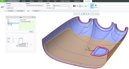
You can now use the new Core Ply command to create a core ply object in the Laminate Tree. A core ply consists of a boundary chain, a material definition, a rosette coordinate system, an orientation angle, the drop-off value, and an optional taper definition. In addition to the required outer boundary loop, you can also include inner loops. You can define a taper on each tangent chain of the outer and inner loops. You can also apply multiple taper values per boundary loop if you select several tangent chains.
To set the default prefixes for the name and sequence of a core ply, click File > Options. In the Creo Parametric Options dialog box, click Applications > Composite. Specify the values under Name Policy Settings. Alternatively, set the following configuration options:
- composite_def_core_name_prefix-Specifies the prefix applied to the name of a new core ply.
- composite_def_core_seq_prefix-Specifies the prefix applied to the sequence of a new core ply.
This enhancement is useful when you design a composite layup. Previously, it was not possible to define a core ply object in Creo. With this enhancement, you can create core ply objects as one of the key laminate objects in a composite design. You can then use it to derive a flat pattern for the manufacturing of the composite part.
Laminate Section, Drop-off, and Color Mapping
Creo Parametric 10.0.1.0
User Interface Location:
- In Composite Design, clickUtilities > Laminate Section.
- In Composite Design, clickSetup > Drop-off.
- In Composite Design, clickSetup > Color Mapping.
You can now use the special Laminate Section command to look inside a composite design and visualize the layup based on the Laminate Tree information that correlates the color coding from the Laminate Tree to the actual section. You can use the scaling option to avoid excessive zooming and better see the very thin plies that compose the laminate design.
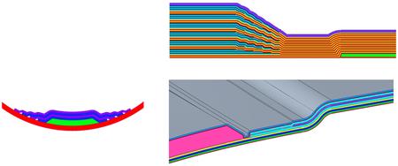
You can use the Drop-off command and define the default drop-off value to control the overall ply and core drop-off behavior over the underlying ply contours in the laminate section, making it easier to see material distribution during the layup.
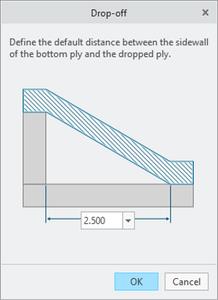
You can use the Color Mapping command to change the system-assigned color coding of plies.
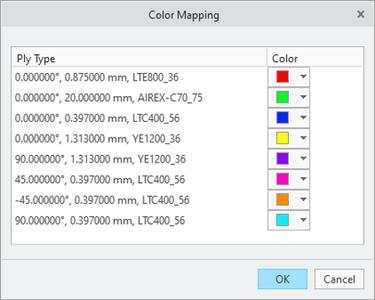
These enhancements are useful when you design a composite layup in Creo and want to visualize the layup in a specific location or section. With these enhancements, you can visualize the detailed interactions and overlaps of the internal plies based on the laminate list information, dynamically updating during the section dragging. You can also scale the ply geometry in the layup direction to enhance the visibility.
Transition Plies
Creo Parametric 10.0.1.0
User Interface Location: In Composite Design, clickPlies > Transition Plies.
You can now use the new Transition Plies command to shorten or extend one or more plies. To create a transition effect for multiple plies, the plies must have at least a partially common boundary from which you can select the transition chain and specify the offset value. This results in an adjustment of the selected ply contours. You can create a profile transition by defining a constant offset value, or create a custom transition by defining variable transition values. You can create multiple Transition Ply features within a Composite feature.
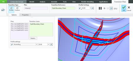
This enhancement is useful when changing the existing ply contours to achieve a gradual change of a laminate thickness or when changing the contour of a single ply by an offset value of selected transition edges. With this enhancement, you can change ply contours without redefining manual plies and locally create a gradual change of laminate thickness.
Splice Plies
Creo Parametric 10.0.1.0
User Interface Location: In Composite Design, clickPlies > Splice Plies.
You can now use the new Splice Plies command to split an existing ply into two new ply pieces by using a curve or edge on the layup surface. You can splice a ply with a butt connection or an overlap connection. You can also stagger the splice location when multiple plies are selected. The splicing curve defines the splicing or darting trajectory. The splicing curve can be an open chain or a closed chain. It must form a closed loop with itself or with the ply boundary. The following examples show various ways in which you can select a splicing curve to splice or dart plies:
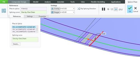
This enhancement is useful for splitting a very large ply into smaller pieces, so that the flat pattern size of these pieces does not exceed the roll width of the material. You can also use splicing to dart a section of a ply so that draping problems, such as wrinkling, are eliminated. This enhancement enables you to define a conceptual large ply and splice it later based on the manufacturing needs, without having to redefine the designed ply.
Draping Simulation
Creo Parametric 10.0.1.0
User Interface Location: In Composite Design,Analysis > Draping Simulation.
You can now use the new Draping Simulation command to analyze the ply producibility and to create the ply flat patterns. Based on the selected seed point, it calculates the fiber distortion while simulating the application of the flat ply onto the mold.
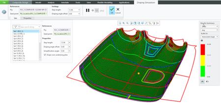
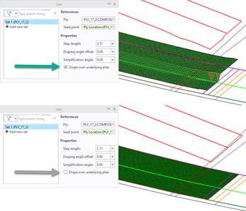
By default, the Drape over underlying plies option is selected, and draping is calculated by considering the context of each ply. This makes the results more accurate and realistic.
While the seed point can be any location on the ply surface area, you can also lock it to an existing datum point. You can make additional refinements by using the property parameters for the step length, drape angle offset, and simplification angle. There are different result types: Shear, Longitudinal Orientation, Transverse Orientation, and Draped Ply Thickness. The Shear results are automatically scaled to the warn angle and limit angle values of the material. Outside the feature dashboard, in the Draping Manager mode of the Laminate Tree, the drape simulation results are shown in a traffic light format. For each ply, the result icon indicates whether the level of shear is under the warn angle , over the warn angle but below the limit angle , or over the limit angle .
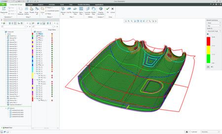
You can preview the draping simulation results and a flat pattern from within the feature dashboard or directly from the Draping Manager mode of the Laminate Tree by selecting the Show Draping Results command on the mini toolbar. The ply flat patterns can be exported to the DXF format. Longitudinal and transverse fiber orientations, due to draping, can be exported to the HDF5 format for use in downstream analysis. You can review the summary report of the draping analysis by using the Export Draping Summary command in the Analysis group.
This enhancement is useful for simulating the draping when you apply the ply to the mold and calculate the fiber distortion (shear) and the flat pattern. This enhancement gives you an insight into the fiber distortion during draping. This enables you to optimize the selected seed point location and the draping direction to get the best possible result. It also enables the creation of the required flat ply contour.
Export Flat Pattern
Creo Parametric 10.0.1.0
User Interface Location: In Composite Design, clickAnalysis > Export Flat Pattern.
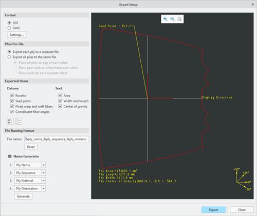
You can now use the new Export Flat Pattern command for the plies with successful drape results to create one or more DXF or DWG files of the flat pattern contours of plies. You can export each ply to a separate file, or export all selected plies to the same file with several options to control the positioning of the contours. Optionally, you can also add several ply properties to exported files.
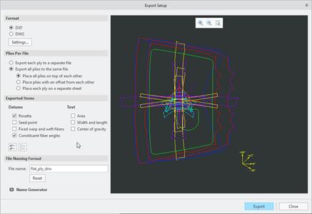
You can use the file name generator for smart file formatting when you export each ply to a separate file
Close
To set the default settings for the options in the Export Setup dialog box, use the following configuration options:
- export_plies_to_dxf_dwg_files-Specifies whether to export each ply to a separate file or to export all plies to the same file.
- export_ply_area_text_to_dxf_dwg-Specifies whether to export textual information about the area of a ply.
- export_ply_cog_text_to_dxf_dwg-Specifies whether to export the textual information about the center of gravity of a ply.
- export_ply_dir-Specifies the default location to store the exported plies.
- export_ply_fiber_ang_to_dxf_dwg-Specifies whether to export the constituent fiber angles of a ply.
- export_ply_fibers_to_dxf_dwg-Specifies whether to export the fixed warp and weft fibers of a ply.
- export_ply_file_format-Specifies the default preferred export file type for the exported plies.
- export_ply_rosette_to_dxf_dwg-Specifies whether to export the reference rosette of a ply.
- export_ply_seed_pnt_to_dxf_dwg-Specifies whether to export the seed point of a ply.
- export_ply_size_text_to_dxf_dwg-Specifies whether to export the textual information about the width and length of a ply.
- exported_ply_file_name-Specifies the default file name for the exported file. When exporting each ply to a separate file, the ply name is automatically added as a suffix.
- plies_placement_in_dxf_dwg_file-Specifies the placement of plies when multiple plies are exported to the same file.
This enhancement enables you to export the flat contour and create one or more flat pattern files. You can later send these files to the nesting or cutting machine.
Ply-based Mass Properties
Creo Parametric 10.0.1.0
User Interface Location:
- In Composite Design, clickSetup > Mass Properties Computation.
- In Composite Design, clickFile > Prepare > Composite Properties.InComposite Propertiesdialog box, click change in the row of Mass Properties.
- In Composite Design, clickAnalysis > Mass Properties.
You can now calculate composite mass properties based on the defined laminate layup, material properties, ply and core boundaries, and the stacking sequence. You can calculate the mass properties of a composite in two ways:

- The mass properties calculation based on the layup surface provides a simple and quick analysis.
- The mass properties calculation based on the underlying plies follows the same approach as in draping simulation. This method considers the shapes of underlying plies and cores, and the overlaps for each sequence step. This method is more time consuming but, is more accurate.

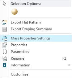
To calculate mass properties of an individual ply, right-click the ply in the Laminate Tree, and select Mass Properties Settings.
To calculate mass properties of the full laminate, click File > Prepare > Composite Properties. In Composite Properties dialog box, click change in the row of Mass Properties.
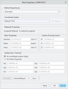
At the part level, the composite feature creates a dedicated body for the composite result, and the ply-based mass properties of the specific layup are assigned to that body. This is independent of any ply-based solidification of the laminate. You can also create a mass properties analysis of a single laminate object or of the full laminate from the Analysis tab. For the calculation, you can select whether to run the analysis based on the layup surface definition, which ignores the context, or based on the underlying plies, which is more accurate.
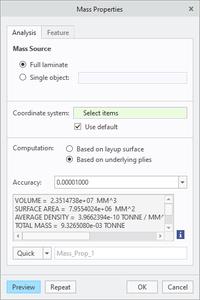
This enhancement is useful for calculating the mass properties of a single ply or of the full laminate layup. With this enhancement, you can obtain ply-based mass properties independently of the solidification of the laminate.
Solidify Plies
Creo Parametric 10.0.1.0
User Interface Location: In Composite Design, clickUtilities > Solidify Plies.
You can now use the new Solidify Plies command to create a ply-based solid representation of the laminate and, optionally, an additional quilt of the outer surfaces of the solid that represents the inner mold line (IML).
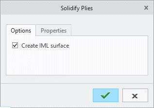
When you exit Composite Design, the solid representation of the laminate is added to the dedicated composite body in the part model. If the Create IML surface check box is selected during the solidification, the composite feature also creates a quilt at the part level.
This enhancement is useful for creating a solid representation of the laminate list. This enhancement enables you to create a ply-based solid model of the full laminate as a deliverable of the composite feature. You can later use the ply-based solid model to represent the final laminate in an assembly.
Export Analysis Model
Creo Parametric 10.0.1.0
User Interface Location: In Composite Design, clickAnalysis > Export Analysis Model.
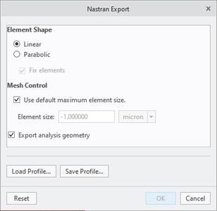
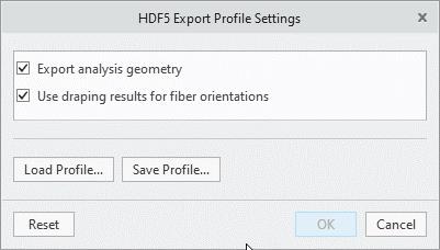
You can now use the new Export Analysis Model command to export the laminate layup definition to Nastran (*.nas) or HDF5 (*.hdf5) format for an analysis in third party applications. To specify additional settings, click Analysis > Export Analysis Model. In the Save a Copy dialog box, select the type of export and click Options.
Close
To improve meshing in third-party applications, Creo generates an IGES file of the layup surface, which is by default split into all resulting model regions. If you do not need an IGES file, clear the Export analysis geometry check box. When you export the laminate layup definition to a HDF5 file, Creo includes the longitudinal and the transverse fiber orientations obtained from the draping results in the HDF5 file by default, for use in downstream analysis. To exclude them, clear the Use draping results for fiber orientations check box.
This enhancement supports sharing of the laminate layup definition with third-party analysis applications. HDF5 export enables the sharing of layup definition with third-party applications for downstream analysis. By default, true ply longitudinal and transverse orientations that are determined from draping simulations are included for the improved accuracy of the analysis.
Ply Book
Creo Parametric 10.0.1.0
User Interface Location:
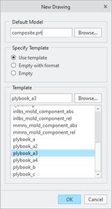
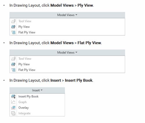
- To create a new ply book, create a new drawing by selecting a composite model as the default model and by selecting a ply book template in the New Drawing dialog box.
Close
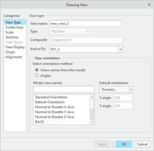
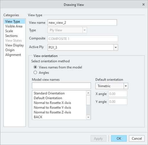
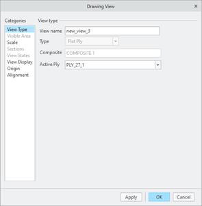
You now can create a ply book document for models with one or more composite features. You can create a new ply book automatically based on a template drawing file, allowing each ply to be represented on its own drawing sheet in the correct sequence order. You can also insert a template-based ply book in an existing regular drawing or a ply book drawing. You can specify the range of plies for which the sheets must be added in the ply book. You can now use the Ply View and Flat Ply View commands to create two new view types, a ply view and a flat ply view, in a drawing that contains a composite feature as the active drawing model. When you create a ply view, you can specify various additional settings to show background plies, laminate sections, and various other options.
xPTC Creo 10.0.1.0 with HelpCenter
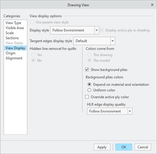
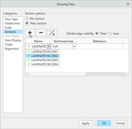
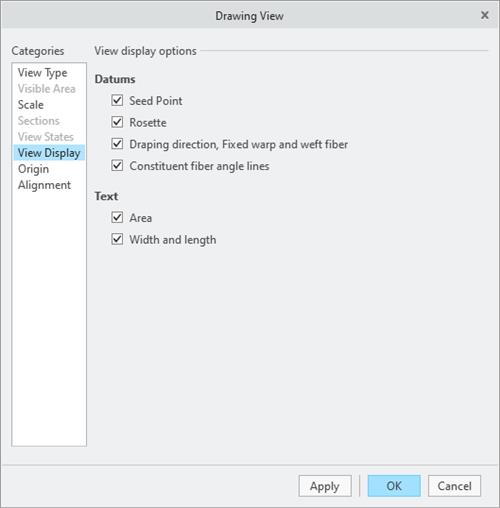
You can create flat ply views only when the plies have successful draping results. When you create a flat ply view, you can show numerous ply property details with the view, such as the rosette, the draping direction, the ply area, and various other options.
Close
This enhancement is useful for automatically creating a ply book, documenting the lamination process, and creating ply-related drawing views in any drawing.
Integrated Composite Analysis
Creo Parametric 10.0.1.0
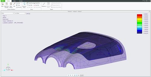
User Interface Location: In Composite Design, clickApplications > Simulate.
Close
This enhancement is useful for analyzing composite structures in Creo. With this enhancement, you can design and analyze composite structures in Creo, without the need to manually assign laminate properties in Creo Simulate.
Detailed Drawings
Configuration Option to Specify the Type of Hatches to Be Converted to PAT
You can now use the new configuration option hatch_pattern_convert_all_xch to specify the type of hatch patterns that should get converted to the PAT format when you run the Convert All XCH to PAT command in drawings.
This enhancement provides you with a better control when converting hatch patterns in the drawings to the PAT format.
Part Modeling
New Rolling Ball option in Offset
- Create complex surface/quilt offsets more easily in situations that could not be offset previously.
- The Rolling Ball option can improve the chances to successfully offset surfaces:
. When surfaces contain high curvature areas (corresponding curvature radius is smaller than the offset value).
. When the offset leads to complex topology changes and self-intersections during offset.
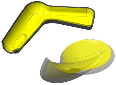
- Special handling makes it possible to exclude remaining problematic surfaces.
- Patching
. During the Offset operation, the mathematical offset calculation might result in surfaces that contain geometric singularities (degenerated areas) that are reported by Geometry Checks, along with single-sided edges.
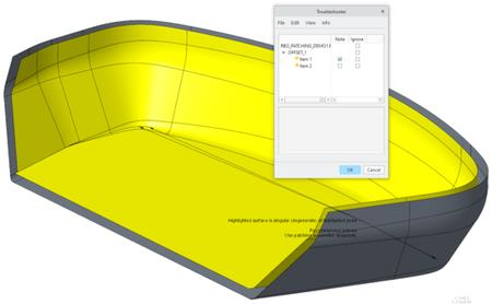
. Use the new Patching option to automatically approximate the area around the potentially resulting geometric singularities with:
.. Residual rounds
.. Droplets
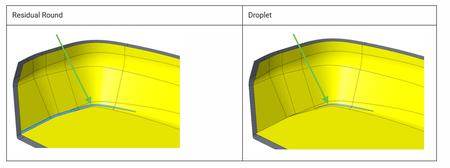
. For both options, the corresponding radius can be specified. Typical patching radii are ~5-20% of the offset dimension.
- Includes enhancements to Round capabilities.
- Boundary handling
. Maintain boundary shape is a new option that controls the geometric result at the boundaries:
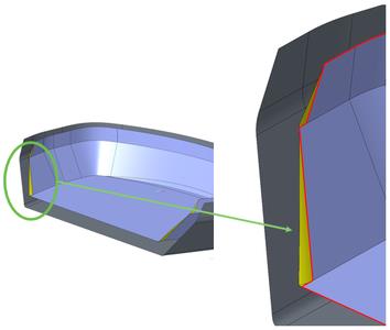
. Red edges: Maintain boundary shape is not selected
. Yellow edges: Changed edges when Maintain boundary shape is selected
.. This option can influence the overall success of the Offset feature, depending on the specific geometric situation.
.. Maintain boundary shape must be selected to make side surface creation available
- Creates offsets more easily where standard offsets fail
- Offsets high curvature geometry
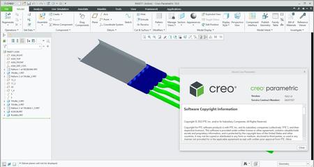
PTC Creois the 3D CAD solution that helps you accelerate product innovation so you can build better products faster. Easy-to-learn Creo seamlessly takes you from the earliest phases of product design to manufacturing and beyond. You can combine powerful, proven functionality with new technologies such as generative design, augmented reality, real-time simulation, additive manufacturing. and the IoT to iterate faster, reduce costs, and improve product quality. The world of product development moves quickly, and only Creo delivers the transformative tools you need to build competitive advantage and gain market share.
PTC is proud to introduceCreo 10 and Creo+, the latest versions of our award-winning, powerful, yet easy-to-use CAD system. Creo helps you deliver your best designs in less time, with new composite tools and enhancements for electrification and ergonomics design, MBD, simulation-driven design, and manufacturing. Creo+, available via SaaS, provides innovative cloud-based tools for real-time collaboration and streamlined license management and deployment.
What's New in Creo 10 and Creo+
PTCenables global manufacturers to realize double-digit impact with software solutions that enable them to accelerate product and service innovation, improve operational efficiency, and increase workforce productivity. In combination with an extensive partner network, PTC provides customers flexibility in how its technology can be deployed to drive digital transformation - on premises, in the cloud, or via its pure SaaS platform. At PTC, we don't just imagine a better world, we enable it.
Rapidgator-->Click Link PeepLink Below Here Contains Rapidgator
http://peeplink.in/36777f8aab2b
Uploadgig
orm7k.setup.part1.rar
orm7k.setup.part2.rar
orm7k.setup.part3.rar
NitroFlare
orm7k.setup.part1.rar
orm7k.setup.part2.rar
orm7k.setup.part3.rar
Links are Interchangeable - No Password - Single Extraction
